What Is a Differential Bypass Valve in HVAC Systems?

Spend enough time around HVAC engineers and you will hear a lot of talk about pressure. Too much of it in the wrong place, and the whole system starts misbehaving. Control valves slam. Pumps run at the wrong duty point. Terminal units either get flooded with water or they starve. None of it is comfortable for the people inside the building, and none of it is good for the equipment either.
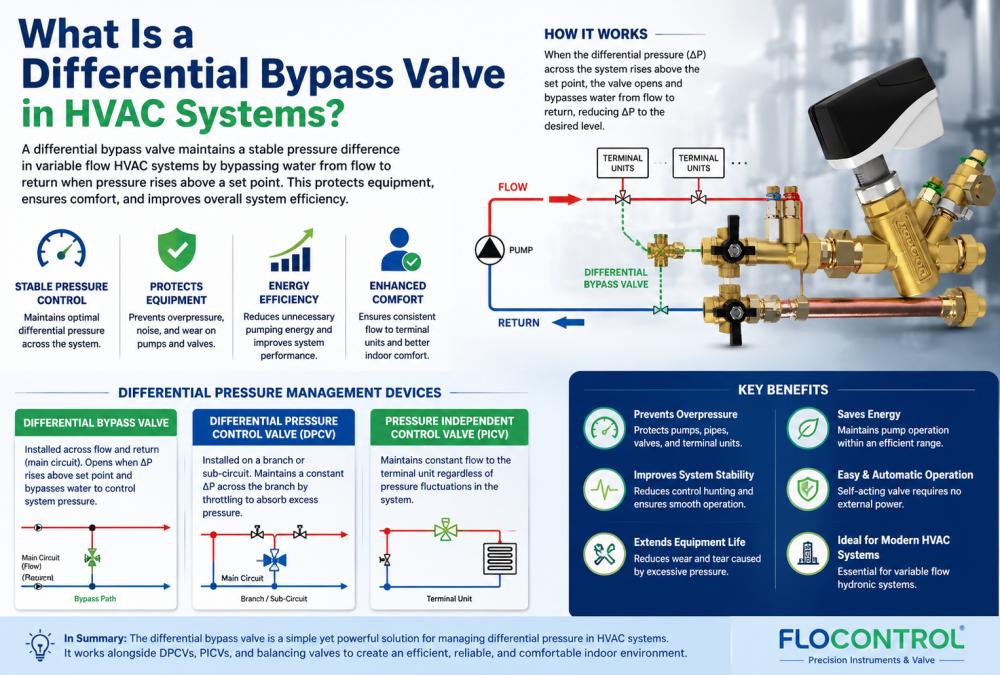
The differential bypass valve is one of the tools that sits at the heart of solving this problem. It is not flashy. You will not find it mentioned in design brochures alongside the chillers and heat pumps. But in a variable flow hydronic system, it quietly does one of the most important jobs in the plant room keeping the pressure difference across the distribution network within limits that everything else in the system can actually live with.
This article breaks down how a differential bypass valve works, how it connects to related technologies like DPCVs, PICVs, and automatic balancing valves, and why the distinction between all these things matters in practice.
The Pressure Problem in Variable Flow Systems
Most modern HVAC systems are variable flow. Rather than pumping a fixed volume of water around the building at all times, the pump speed changes based on demand. When rooms need less heating or cooling, control valves on the terminal units close down. Less water flows. The pump slows. Energy is saved. In theory it is elegant, and in practice it works well but it creates a challenge that older constant flow systems never had to deal with.
When control valves close down, the flow path for the water narrows. The pump is still running, still generating pressure. But with fewer routes for the water to travel, that pressure has to go somewhere. It builds up across the distribution pipework. In a system with ten terminal units and eight of them calling for no flow, the two that are still open are suddenly seeing a much higher differential pressure across them than the design intended. The control valves on those units get pushed harder. Flow shoots up. The control loop goes unstable. The room temperature oscillates instead of settling.
This is the core problem that differential pressure management is trying to solve. The differential bypass valve is one answer to it and understanding how it works helps make sense of the other solutions too.
How a Differential Bypass Valve Actually Works?
A differential bypass valve sometimes just called a bypass valve or a pressure relief valve in this context is installed across the flow and return headers of a hydronic system, usually somewhere near the pump. Its job is simple to describe even if the execution involves some careful engineering: when the pressure difference between flow and return rises above a set point, the valve opens and allows water to bypass directly from flow to return, effectively short-circuiting the distribution loop.
By letting water pass back without going through any terminal units, the valve reduces the effective resistance in the system. The pump, now finding a lower resistance path, settles back to a duty point that is closer to what it was designed for. The differential pressure across the distribution network drops back toward the set point. The control valves on the remaining open circuits stop being hammered by excess pressure and start behaving predictably again.
The valve itself responds to differential pressure mechanically or via a control signal, depending on the type. A self-acting differential bypass valve uses the pressure difference directly to actuate the valve plug with no controller, no power supply, no signal cable needed. The higher the differential pressure rises above the set point, the further the valve opens, and the more water it diverts. When demand picks back up and control valves reopen, the bypass closes again. It tracks the system continuously and automatically.
Electrically actuated versions exist too, typically used where the bypass valve needs to be integrated with a wider building management system or where more precise control of the set point is needed. These allow the target differential pressure to be adjusted remotely and can be incorporated into optimisation strategies that vary the set point based on which zones are active.
Where Does the DPCV Fit In?
A Differential Pressure Control Valve usually shortened to DPCV does a related but distinct job. Rather than managing the overall system pressure by bypassing flow at the plant, a DPCV is installed on a branch or sub-circuit within the distribution network. Its role is to maintain a constant differential pressure across that branch, regardless of what the rest of the system is doing.
Think of a large building with multiple risers, each serving a floor or a zone. If one zone calls for maximum flow while another closes down almost entirely, the pressure distribution across the network shifts. Without control, the riser that still has open circuits sees a higher differential than intended. The DPCV on that branch absorbs the excess by throttling; it adds resistance to bring the differential back to the target. The terminal units downstream of it carry on receiving the pressure they were designed to see, even though the network around them is changing.
DPCVs are self-acting in most installations. They have a pilot connection that senses the pressure downstream, and the valve adjusts its opening to maintain that pressure. They need no external power to do this, which is part of what makes them reliable and attractive from a maintenance perspective. Set them correctly during commissioning, and they do their job without much further attention.
The relationship between the differential bypass valve and the DPCV is one of layers. The bypass valve manages the bulk system pressure at the plant. DPCVs manage the branch pressures deeper in the distribution tree. Used together, they give you tight control at every level of the system.
Pressure Independent Control Valves — The PICV
The Pressure Independent Control Valve, or PICV, takes the idea further still. Where a DPCV protects a whole branch, a PICV works at the level of the individual terminal unit: a fan coil, an air handling unit, an underfloor heating manifold. Inside a single valve body, it combines three functions: differential pressure regulation, flow limitation, and control actuation.
The pressure regulation element works similarly to a DPCV; it absorbs excess differential pressure so the valve always operates within its design range. The flow limitation element sets the maximum flow that can pass through, regardless of how far the control signal opens the valve. And the control element modulates that flow between zero and the set maximum in response to the room thermostat or BMS signal.
What this means in practice is that a PICV delivers a consistent, predictable relationship between the control signal and the flow rate, regardless of what the network pressure is doing around it. This is the pressure independent part of the name. Turn the control signal to fifty percent open, and you get fifty percent of the design flow, not sixty-five percent because the differential pressure has climbed, not thirty percent because the pump is running at low speed. The flow tracks the signal cleanly.
For building operators and commissioning engineers, this is genuinely useful. It simplifies commissioning significantly because the flow limiting function replaces the need for a separate commissioning valve set on each circuit. It also makes the building's thermal response more predictable, which is good for comfort and for the control logic. The BMS does not have to compensate for hydraulic drift; the valve handles it internally.
The trade-off is cost. PICVs are more expensive per unit than a conventional control valve with a separate commissioning valve. On a large project with hundreds of terminal units, that difference adds up. The question engineers have to weigh is whether the improved performance and simplified commissioning justifies the higher upfront cost and for most commercial buildings of any complexity, the answer increasingly is yes.
Automatic Balancing Valves — Sitting Alongside All of This
Automatic balancing valves sometimes get confused with DPCVs, and it is easy to see why the terminology overlaps. An automatic balancing valve is essentially a flow-limiting device that maintains a constant flow rate through a circuit regardless of the pressure available across it. Rather than controlling differential pressure, it controls flow directly.
Inside the valve, a spring-loaded cartridge responds to changes in differential pressure by opening or closing to keep the flow rate steady. If the pressure across the valve rises because a neighbouring circuit has closed down and more pressure is now available the cartridge moves to add resistance and hold the flow at the set rate. If the pressure drops, the cartridge opens further to maintain the same flow. The result is a circuit that draws its design flow rate across a fairly wide range of system conditions.
Automatic balancing valves are particularly useful in systems where the distribution pressure varies widely exactly the situation created by variable flow operation. They remove the need for static balancing across circuits because they balance themselves dynamically. The commissioning process is simpler, and the system maintains its balance as conditions change over time, rather than drifting back toward imbalance as a statically balanced system sometimes does when control valve positions shift.
They are also worth considering in refurbishment projects where the existing distribution network was balanced under different load conditions. Retrofitting automatic balancing valves on a circuit-by-circuit basis can restore hydraulic balance without the need to re-commission the whole system from scratch.
Choosing the Right Combination
The honest answer to which of these technologies to use is that it depends on the system and what you are trying to achieve. For a simple two-pipe heating system in a small building, a differential bypass valve at the plant and some well-set commissioning valves on each circuit might be entirely adequate. For a large commercial building with variable speed drives, multiple zones, and a sophisticated BMS, you are probably looking at a combination of bypass valves, DPCVs on the risers, and PICVs at each terminal unit.
What matters most is understanding what each component controls and making sure the layers of control work together rather than fighting each other. A PICV cannot compensate for a system where the plant differential pressure is so high that the pressure-regulating cartridge is permanently slammed shut. A DPCV on a branch cannot help if the overall network pressure is allowed to swing so wildly that the branch pressure regularly falls outside the DPCV's operating range. Good hydraulic design still requires thinking about the system as a whole.
Engineers who spend time on this thinking who specify the right differential bypass valve set point, who place DPCVs where the network branches, who choose PICVs for critical or complex zones produce buildings that commission cleanly, run efficiently, and stay comfortable. The components themselves are only as good as the thinking behind how they are applied.